Lab 2: Buttons!
- Jack Plantz
- Sep 20, 2018
- 2 min read
In this lab I learned how to use an Arduino to receive digital input, and how to use this to control LEDs digitally.

Materials:
- Arduino compatible board
- Breadboard
- Momentary push-button
- 2 LEDs
- 2 220 ohm resistors
- 1 10k ohm resistor
- Jumper wires
- 1/8th inch Acrylic sheet (scrap from engineering center)
Part 1 - Building the Circuit

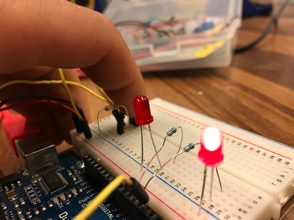
I followed this schematic from the lab write-up to construct a circuit on my breadboard. It uses a pull-down resistor connected between one side of the switch and ground, with the pin of the Arduino connected to the same terminal of the switch. The other side of the switch is connected to power. The effect of this circuit is that the pin of the Arduino reads a low voltage (0) when the button is not pressed and a high voltage (1) when it is. The LEDs are connected with a resistor (to have the correct amount of current and voltage flow through them) to their own pins of the Arduino. This allows them to be individually controlled by a program on the Arduino.
Part 2: Programming

Above is a screenshot of my code that runs on the Arduino. It is a very simple program that defines the pins that each of the circuit elements are connected to, and changes which LED is illuminated depending on whether or not the button is pressed. When the button is not pressed, led1 is set to HIGH and led2 is set to LOW. When the button is pressed, led2 is set to HIGH and led1 is set to LOW.

Part 3: Enclosure

To enclose my project, I built a simple laser cut box from acrylic with a large button on the side. I used makercase.com to generate a laser-cuttable with the correct dimensions to hold my Arduino and breadboard, then measured the holes that needed to be cut to fit the large button and the power cord to my computer and drew those in Adobe Illustrator.

I wanted to make a case for my Arduino that could be used in many projects, not just this one. So I didn't glue the top of the box on, it just rests snuggly with the teeth cut into the sides of the box. This will allow me to use this box in the future with different tops for different needs. Below is an image of the final project:

The large button functions exactly like the small button on the breadboard, it just connects or disconnects the its two input pins. Thus my code runs the same in my enclosure, and my circuit diagram is the same.


Comments